How do we diagnose and optimize the BP585 bandpass filter wavelength shift in PCR systems?
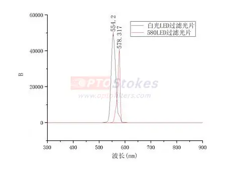
During the assembly and calibration of real-time Polymerase Chain Reaction (real-time PCR) diagnostic equipment, optical design engineers and procurement teams frequently encounter a critical issue: a discrepancy between the nominal optical parameters of a filter and its actual measured performance within the instrument. Recently, OPTOStokes investigated a case study from a PCR device manufacturer. The client integrated a BP585 bandpass filter into their fluorescence detection system, but spectral testing within the instrument revealed that the center wavelength (CWL) shifted dramatically down to approximately 554nm. This unexpected 31nm deviation raised immediate concerns regarding filter quality and its potential impact on the precision of multiplex qPCR fluorescence channels.
As a leading global manufacturer of precision optics, the OPTOStokes engineering team conducted a comprehensive on-site operational context analysis. The diagnostic data confirmed that the spectral shift was not caused by any manufacturing defects, pinholes, or coating degradation of the thin-film elements. Instead, it was a classic manifestation of an optical blue shift induced by an unoptimized light source path design—a high-frequency integration failure in modern PCR fluorescence subsystem engineering.
The Physics of Blue Shift: How Incident Angles Modify Thin-Film Interference
To identify the root cause, it is essential to examine the system's illumination setup. The client’s instrument utilizes a high-power white LED as the primary excitation source, which is standard in cost-effective PCR instrument designs. However, the critical engineering omission was the complete absence of a collimating lens assembly between the light source and the optical filter array.
Standard white LEDs are inherently highly divergent emitters, typically exhibiting a natural Lambertian distribution with half-power angles (divergence angles) up to 120°. Without optical regulation, this highly divergent light impinges upon the surface of the BP585 bandpass filter across a broad spectrum of oblique angles. From the principles of thin-film optics, hard-coated Bandpass Filters rely on constructive and destructive interference across multiple nano-scale dielectric layers. The spectral transmission specifications of these interference coatings are precisely calibrated for parallel light at a 0° Angle of Incidence (AOI).
When divergent, multi-angle light rays enter the optical thin-film structure, the optical path length within the low and high refractive index layers is altered. This geometric path reduction systematically shifts the filter's transmission profile toward shorter wavelengths. This physical phenomenon is governed by the following interference equation:
λθ = λ0 × [1 - (sin2θ / neff2)]1/2
Where λθ represents the center wavelength at an angle of incidence θ, λ0 is the center wavelength at 0° AOI, and neff is the effective refractive index of the thin-film coating stack. As the divergence angle (θ) increases, the center wavelength moves rapidly to the shorter spectrum (blue shift). Beyond the wavelength shift, wide-angle oblique incidence causes severe degradation of the spectral profile, including slope distortion, increased passband ripple, and a significant drop in peak transmittance (T%). For PCR applications, this distortion leads to weak excitation efficiency, severe cross-talk between dye channels (e.g., VIC/HEX leaking into FAM or TAMRA channels), and a drastic drop in the signal-to-noise ratio (SNR) of the automated diagnostic system.
Comparative Analysis: Non-Collimated vs. Collimated Optical Paths
The table below details the performance comparison of the BP585 filter under non-collimated divergent light versus parallel optical conditions:
| Optical Parameter / Metric | Non-Collimated Setup (120° Divergent LED) | Collimated Setup (0° AOI Target) | Impact on PCR Diagnostics |
|---|---|---|---|
| Center Wavelength (CWL) | ~554 nm (Severe Blue Shift) | 585 ± 2 nm (Nominal) | Misalignment with target fluorophore emission. |
| Peak Transmittance (T%) | Dropped to <65% | ≥90% (High Transmission) | Attenuated fluorescence signal, leading to high Ct values. |
| Spectral Edge Steepness | Degraded, rounded slopes | Ultra-sharp OD6 blocking transitions | Increased multi-channel cross-talk and background noise. |
| Fluorescence Quantification | Unstable, high false-negative rate | High precision, repeatable quantification | Ensures system reliability and clinical diagnostic accuracy. |
The Engineering Solution: Integrating a High-Precision Collimating Lens
To resolve the wavelength shift without redesigning the core thin-film coating profile, OPTOStokes deployed a standardized engineering fix: integrating a high-numerical-aperture (NA) optical collimating lens assembly directly between the white LED source and the BP585 filter element.
The collimating lens captures the 120° divergent wavefronts emitted by the LED die and reshapes them into a highly ordered, parallelized beam. By reducing the maximum incidence angle on the filter surface to within ±3° AOI, the physical conditions match the original 0° perpendicular optical design specifications. Following the implementation of this collimation upgrade, subsequent spectral testing showed that the filter restored its nominal center wavelength of 585nm with peak transmission exceeding 92%, completely eliminating the channel cross-talk anomaly.
Partner with OPTOStokes for Advanced PCR Optical Optimization
Engineering robust life-science instrumentation requires deep synchronization between component performance and optical system geometry. For R&D engineers, procurement managers, and OEM decision-makers, anomalies encountered during instrument prototyping are rarely isolated component defects; instead, they are systemic integration challenges such as misaligned AOI, polarization-dependent losses, or out-of-band stray light leakage.
OPTOStokes provides a comprehensive ecosystem designed to de-risk your instrument development pipeline. Our capabilities address the core pain points of modern biomedical device manufacturing:
Extensive In-Stock Catalog for Rapid Prototyping: We maintain a massive inventory of ready-to-ship components, including specialized PCR Optical Filters, dichroic beamsplitters, and excitation/emission pairings, allowing engineering teams to bypass long manufacturing lead times during critical proof-of-concept stages.
High-Level OEM Customization: If your system layout imposes fixed tilt configurations (e.g., 12° or 45° AOI for compact multi-channel designs), our coating engineers can pre-compensate for spectral blue shifts by modifying the physical thickness and composition of our hard-coated thin films during deposition.
World-Class Quality and Predictable Lead Times: Leveraging automated planetary deposition platforms and advanced plasma-assisted sputtering technology, OPTOStokes guarantees excellent run-to-run uniformity, minimal thermal drift, and robust environmental durability. Our optimized production infrastructure ensures reliable delivery schedules for scale-up manufacturing.
Accelerate your system's path to commercial mass production. For customized technical consulting, detailed spectral data sheets, or to request qualified samples of our matched Fluorescence Filter Sets, contact our application engineering desk directly via email at sales@optofilters.com. Our technical support team will provide cross-disciplinary assistance from optical path modeling to custom fabrication layouts.