
How to judge the front and back of a filter: first distinguish the coating structure, and then determine the orientation of the film surface
The answer to whether there are positive and negative filters is not "yes" or "no", but "it depends on the coating architecture". The filter with single-sided functional film coating has clear positive and negative directions, and the functional film must face the light source; Both sides are coated with functional film, and both sides are involved in the work, with the direction determined by design and marking; The dichroic mirror must be installed at a 45 ° angle with the coating facing the specified direction. When discussing three situations together, there will be a situation where 'pretending to follow a certain experience, the result is still wrong'.
1、 First confirm the structure: two coating architectures and two sets of rules
| Architecture | Incident surface | Exit surface | The role of both sides |
|---|---|---|---|
| Type A (standard type) | Functional film (interference filter film) | Anti reflective film | One side performs spectral selection, while the other side reduces interface reflection loss |
| B-type (double-sided functional type) | bandpass film | blocking film | Both sides participate, and the second side performs secondary suppression of out of band energy |
The statement circulating in the market that "alternating high and low refractive index film layers are deposited on both sides of the substrate" is not accurate. The standard bandpass filter is coated with dozens of layers of interference film on one side and anti reflection film on the back; The B-type, which divides functions into two sides, also exists for situations that require higher blocking. The installation directions of the two architectures are different, so the first thing to confirm is not "which side is bright", but which type of specification this specification belongs to - if the data sheet is not written, ask the supplier for it, which cannot be seen by the naked eye, because the appearance of the anti reflection film and the blocking film under indoor light can be exactly the same.
2、 Why does the functional film face the light source?
The reason is half optical and half thermal. When out of band stray light hits the functional film, it will be reflected back to the direction of the light source and will not enter the substrate at all; If the substrate does not bear the blocking load, it will not heat up and will not produce broad-spectrum spontaneous fluorescence due to heating.
After installation, the order is reversed: the strong light outside the band first passes through the substrate and is absorbed inside the glass, and then the film layer stops it. The consequence is not that it cannot be stopped, but that it is stopped too late - the glass heats up, the spontaneous fluorescence rises, the background becomes dirty, and the signal-to-noise ratio decreases. In fluorescence systems, this loss is often misdiagnosed as light source attenuation or detector aging, and even if the wrong component is replaced, the cause cannot be found. So when judging the orientation, instead of worrying about the difference in transmittance, it's better to remember one sentence: let the stray light be reflected before entering the glass.
3、 How to determine which side is the membrane surface?
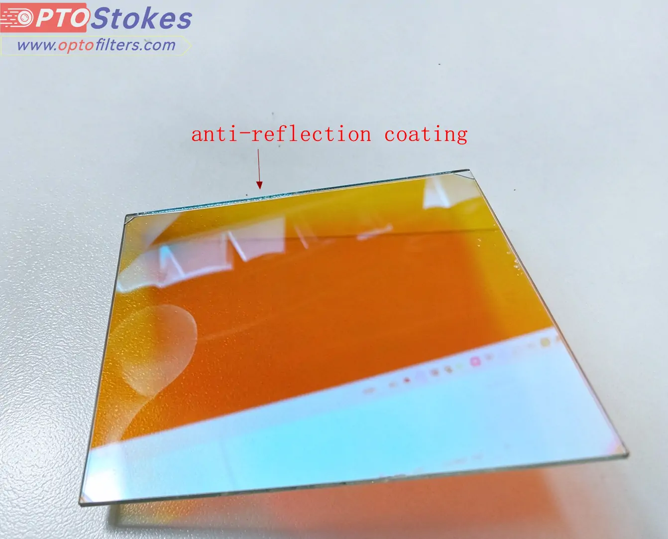
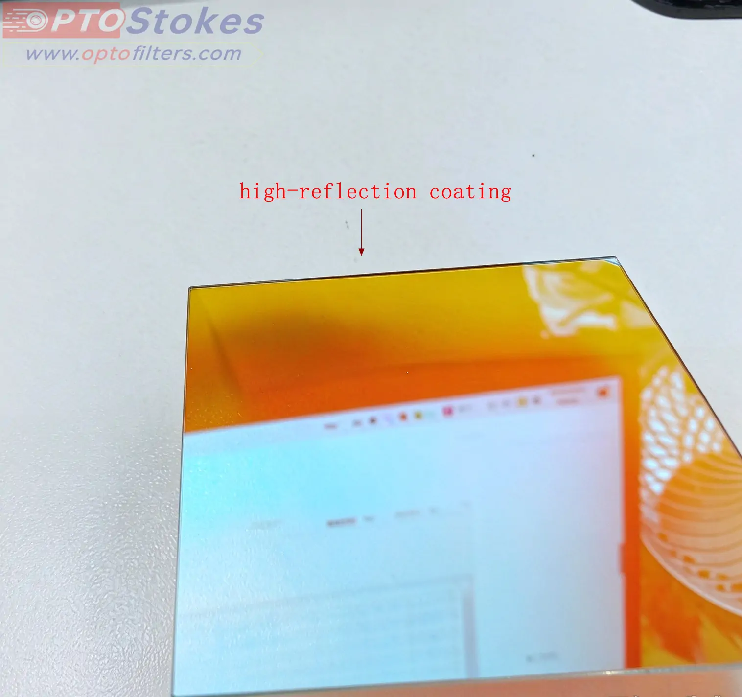
The most reliable thing is the marking, not the appearance. There are two conventions in the industry with completely different meanings: arrows indicate the direction of light propagation, with the tail end entering and the tip exiting; Triangles or dots represent the position of the coating surface, only indicating the position and not the direction. Mixing these two is the most common reason for on-site installation - arrows tell you where the light is going, and triangles tell you which side the film is on. These are two things.
When there is no marking, the lens can be observed at an angle: the interference film surface will show a clear film color at an angle of inclination, which will change color with the angle; The reflectivity of the anti reflective surface is low, the color is dark, and the changes are not obvious. This method is only effective for type A. Type B has functional films on both sides, and when viewed at an angle, there is also a film color that cannot be distinguished by appearance. It is necessary to check the markings or drawings.
Judging the pros and cons based on the depth of color is not valid. The color of the film system is determined by the design and has no corresponding relationship with "which side is the functional side"; Changing the design of the same batch of products may result in a reversal of depth. When encountering situations where the identification is unclear or the drawings are missing, reporting the batch number to the original factory for confirmation is much faster than checking again after three installations.
4、 What will happen if the equipment is reversed
| Impact item | Has there been a change | Reason |
|---|---|---|
| passband blocking depth (OD) | basically unchanged | No matter from which side the light enters, it must pass through the entire membrane system to reach the detector |
| Center wavelength | Unchanged | Blue shift is determined by the incident angle and the effective refractive index of the film system, and is independent of orientation |
| Background to signal-to-noise ratio | Significant deterioration | Out of band light enters the substrate first, is absorbed and generates heat, and the substrate produces spontaneous fluorescence |
| Ghosts and glare | Deterioration | Multiple reflections are formed between the two surfaces of the substrate, resulting in a secondary optical path |
| Membrane lifetime at high power | Deterioration | The heat load falls on the substrate rather than the outside of the membrane, and the heat dissipation path changes |
This table is worth comparing because it overturns two widely circulated claims. One is that 'reverse installation will make the blockage ineffective' - no, OD is a property of the membrane system itself, regardless of where light enters from. The second is that "reverse installation will cause center wavelength drift" - it is not true, wavelength drift is only related to the incident angle. The true cost of reversing lies in heat and stray light: lifting the background, making ghosting more pronounced, and the film layer is more prone to damage under strong light.
The empirical value of the incident angle mentioned in the original text can be used as a reference: the difference in transmittance curves between the front and back of the device is very small near normal incidence (approximately within 15 °), and the difference gradually becomes apparent when the maximum incident angle reaches 45 ° or belongs to a large field of view oblique incidence. This range comes from engineering experience, not actual measurement conclusions. For a specific product, the angle characteristic data provided by the manufacturer should still be used as the standard.
5、 A dichroic mirror is another matter
The rules above cannot be applied to dichroic mirrors. It is used at a 45 degree tilt, with one side reflecting the excitation band and the other side transmitting the emission band. The consequence of reverse installation is not "dirty background", but the color separation function is directly reversed. The recognition feature is very clear: the excitation light leaks towards the detector, and at the same time, the fluorescence signal drops sharply - seeing this combination, first check the direction, without checking the light source.
There are three installation points: the lens should be at a 45 ° angle to both optical paths, and the card holder should not be tilted; The coating surface faces the excitation light input side; The marked triangle remains on the same side as the coated surface. <a href=" https://www.optofilters.com/product/DichroicMirror.html The color separation edge position of a dichroic mirror is extremely sensitive to angles, and a few degrees of installation deviation is enough to offset the edge, which is completely different from ordinary bandpass filters.
6、 Two easily overlooked details
One is that the filter should not be tightly attached to the detector window. Two surfaces pressed together will form a standard fixture, generating spectral ripples that appear as fixed interference fringes in the image and cannot be removed by post-processing. Leave some air gap to avoid it.
Secondly, double-sided coating does not mean there are no positive or negative sides. The B-type has different functions on both sides, and there is a cost when installed upside down. However, the cost changes from "substrate heating" to "reversing the order of blocking levels", resulting in a more concealed performance. This type of product must rely on markings or drawings, do not guess based on appearance.
7、 What to do when the identification is unclear
Don't guess. Provide the model, batch, and usage path (light source type, incident angle, detector position), and ask the original factory to provide installation instructions for the corresponding batch. The orientation rules of the three components (excitation plate, emission plate, and dichroic mirror) in the fluorescence system are different and cooperate with each other. The correctness of each component should be viewed along the entire optical path=“ https://www.optofilters.com/article/industry-Insights/Fluorescence-Filter-Cube-Assembly-.html There is a complete verification sequence for the installation direction of the fluorescent filter group, which can be used for comparison.
If it is already installed but there is suspicion of orientation issues, there is an extremely low-cost on-site discrimination method: the background presents uniform fog and high noise, and the signal is significantly improved after flipping the filter, then it is basically an orientation issue, unrelated to the light source and detector. This test can be completed in five minutes, which is more cost-effective than changing lights or detectors.
Need to confirm specifications or orientation issues
Provide the model, batch, light source type, incident angle, and installation method, and we can provide directional guidance based on the membrane structure of the batch; Customization of dimensions, installation of card rings, or adjustment of film surface markings can also be explained together. Technical Consultation and Inquiry: sales@optofilters.com Please refer tofor the complete category=“ https://www.optofilters.com/product/OpticalFilters.html Classification of Optical Filter Products