
Clear center and dark edges: These dark corners are usually unrelated to the quality of the coating
In industrial vision systems with 808nm active illumination, it is common to encounter problems such as normal contrast in the center of the image, obvious darkening at the edges, and errors in depth information and feature recognition in the edge areas, resulting in unstable production line detection results. Therefore, customers often remove the filter and retest it. The peak transmittance, central wavelength, and blocking depth are all within the specification range. Replace it with a piece of the same specification and find the same problem.
So we can basically rule out the problem of poor coating. So the direction needs to be turned to the incident angle.
The edge field of view of a wide-angle lens with a large field of view usually has the principal ray passing through the optical path with an inclination angle. If the filter is installed in front of the lens, it faces a continuous angle distribution from 0 ° to the maximum field of view, rather than a single angle. The passband position of the interference filter varies with the incident angle, so the center and edge of the image actually work with two different curves - while the CWL, FWHM, and OD on the specification table are all given under 0 ° conditions.
This type of failure occurs frequently in machine vision scenes. When selecting, only check if the nominal wavelength matches, and only discover it after installation=“ https://www.optofilters.com/article/industry-Insights/Angle-of-Incidence-Effect-on-Optical-Filters-.html The impact of incident angle on the performance of the filter is much greater than expected, which is one of the main reasons.
How big is the blue shift: it needs to be calculated first and then judged
The center wavelength of the interference filter will shift towards the short wave direction with the incident angle. In engineering, this approximate relationship is used to estimate: λ (θ)=λ 0 ·√ (1 − (sin θ/n_eff) ²), where n_eff is the effective refractive index of the film system. The actual value of multilayer dielectric films is usually between 1.6-2.0. Taking 1.8 as an estimate, the drift of an 808nm product at several key angles is roughly as follows: 10 ° is about 4nm, 15 ° is about 8nm, 20 ° is about 15nm, 25 ° is about 23nm, and 28 ° is about 28nm
This relationship is non-linear. The angle increased from 20 ° to 28 °, only adding 8 °, but the drift increased from 15nm to 28nm, almost doubling. So the intuitive judgment that 'the edge angle looks small' is not accurate here and must be replaced with numerical calculations. When the membrane system design is different, there will be a shift in n_eff, and the actual drift amount will also vary, but the magnitude and trend will not change.
The reverse is also true and more useful: if drift has already been measured, the actual effective angle can be inferred, θ = arcsin[n_eff · √(1 − (1 − Δλ/λ0)²)]。 Taking the 808nm product as an example, the measured drift of 13nm corresponds to an effective incident angle of about 19 °, and the drift of 28nm corresponds to about 28 °. When diagnosing on-site problems, this backtracking is much more effective than arguing about 'what is the approximate angle'.
Need to convert the angle into bandwidth margin
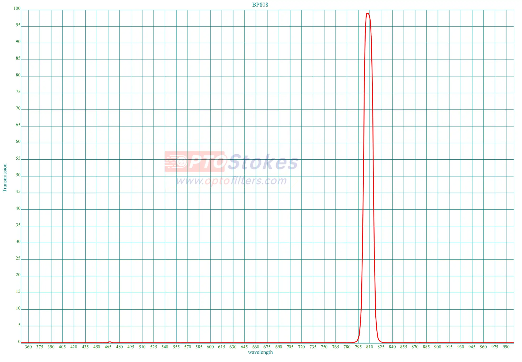
The appearance of dark corners depends on whether the passband of the edge field of view covers the light source band or not. The filter defined by 0 ° shifts the entire passband left by Δ λ at the maximum angle θ m. To keep 808nm within the passband, at least FWHM/2>Δ λ must be met, which means the bandwidth should not be less than twice the drift.
Theoretical minimum FWHM
| Maximum incident angle | CWL blue shift | Actual usable judgment | |
|---|---|---|---|
| 10° | About 4nm | About 8nm | Adequate 13nm product margin |
| 15° | About 8nm | About 16nm | 13nm is at the critical level, and after taking into account the tolerance, the edge will fall off |
| 20° | About 15nm | About 30nm | Need to be relaxed to above 30nm |
| 25° | About 23nm | About 46nm | The bandwidth has approached broadband, and the suppression ability has significantly decreased |
| 28° | About 28nm | Approximately 56nm | Relying on bandwidth coverage is no longer economical, priority should be given to changing the optical path |
This table illustrates one thing: the same 13nm bandwidth is suitable for narrowband design within 10 °, but above 20 ° it becomes a systemic defect. Bandwidth itself is not good or bad, only whether it matches the angle or not. The actual value still needs to be adjusted by adding the spectral width of the light source and the coating tolerance to the theoretical lower limit, leaving a margin.
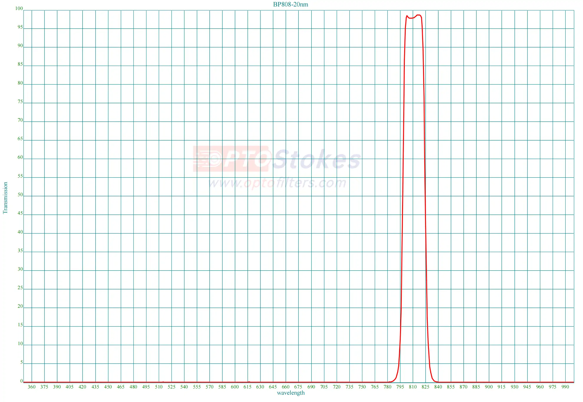
On the scale of 28 °, widening the bandwidth is no longer feasible
The bandwidth is wide enough to cover the edge field of view, which means that the passband width is close to or even exceeds the ambient light interval that needs to be suppressed. A 56nm "narrowband" filter has weak suppression ability for 808nm active lighting: workshop lighting, sunlight and other out of band energy will enter in large quantities, and the contrast of the central field of view will decrease instead. More importantly, bandwidth and blocking depth are mutually constrained - the wider the passband, the more difficult it is to achieve out of band suppression under the same number of membrane layers. To maintain OD4 or higher, it is often necessary to thicken the membrane system or even composite absorbent substrates.
So the problem becomes: if the actual effective incident angle is indeed close to 28 °, then replacing 13nm with 25nm can only cover a part of the field of view, and the edges cannot be completely restored to the center level. On the other hand, if the dark angle does disappear after changing to 25nm, it is more likely to indicate that the actual effective angle is between 15 ° -20 °, and 28 ° is the object field of view angle rather than the true incident angle at the filter. These two angles have a significant difference in the wide-angle system and are worth checking back - using the inverse formula above, a set of measured drift data can provide a definitive conclusion.
Three solutions, in descending order of cost
1、 Change installation position: Let the filter work in the folded beam of light
The common practice for industrial cameras is to install the filter in the threaded interface between the lens and the sensor. The light at this position has been condensed by the lens, and the incident angle is mainly determined by the F-number, rather than the object field of view angle. The angle between the edge principal ray and the optical axis of the F/2.8 lens is about 10 °, and the actual incident angle is slightly larger after superimposing the aperture cone angle; F/4 and F/5.6 are smaller. By lowering the angle, narrow bands like 13nm immediately have a working margin, and there is no need to sacrifice ambient light suppression.
The cost of this path is the lowest, but the premise is that the mechanical structure allows for: whether the intercept is sufficient, whether there are threaded positions, and whether the thickness of the filter will hit the sensor protective glass or pressure ring, all of which need to be measured first. The solution of installing the filter in front of the lens is usually to facilitate the replacement of the filter or avoid obstructing the field of view, but it precisely places the filter in the position with the largest angular distribution - convenience and spectral performance are directly in conflict here. <a href=" https://www.optofilters.com/machine-vision-filters In the selection page of machine vision filters, mechanical dimensions and installation forms are usually listed alongside optical parameters, and this is also the reason why.
2、 Define CWL from a work perspective
If the angle cannot be changed, the supplier can define the center wavelength under the specified AOI and deliberately set the 0 ° CWL to the long wave side, so that the working angle falls exactly at 808nm. This angle compensation is suitable for situations where the full field of view angle is close, such as fixed angle beam paths or single incident angles in scanning systems.
For imaging fields with a continuous distribution from 0 ° to 28 °, it cannot solve the problem: compensating for the edges causes the center to deviate; The center is aligned, but the edges still fall off. This is a geometric constraint, not a coating capability issue. No other supplier can bypass it. The criterion for judgment is simple - if the incident angle span within the field of view multiplied by the blue shift coefficient exceeds the bandwidth, a single filter cannot be consistent across the entire field of view.The sorting order of edge dark corners has a greater impact on efficiency than the parameters themselves. The following items can be confirmed in order to locate the problem in terms of angle and bandwidth:
| Project | What needs to be confirmed | Why is it crucial |
|---|---|---|
| Installation position of filter | In front of the lens, or between the lens and the sensor | Deciding whether the incident angle is controlled by the object's field of view angle or the F-number is a prerequisite for all subsequent calculations |
| Maximum incidence angle | Calculated based on installation location and F-number, or inferred from actual measurements, without using object field of view angle as a substitute | The only input for the blue shift quantity is incorrect, and all subsequent steps are incorrect |
| Effective angle reversal | Reverse calculate the actual CWL drift and compare it with the design assumption | Verify whether the angle judgment is valid and avoid selecting based on incorrect assumptions |
| Spectral width of light source | VCSEL/laser diode/LED, and FWHM value | Determine the lower limit of bandwidth together with the blue shift amount |
| Bandwidth margin | FWHM ≥ 2 x blue shift+light source width+coating tolerance | Directly determine whether the edge field of view still covers 808nm |
| Blocking depth and interval | OD value+corresponding band, does it cover visible near-infrared | Can the additional ambient light be suppressed after the bandwidth is relaxed |
| Transition zone definition point | Mark based on T50% or OD starting point | Can the supply curve match the acceptance criteria |
| Mechanical interface | Thickness, thread specifications, and rear intercept allowance | Deciding whether the low-cost solution of "changing location" is feasible |
If you have specific installation positions, F-numbers or field of view angles, light source types, and current specifications on hand, you can send them to sales@optofilters.com 。 Calculating the bandwidth margin from an angle is faster than repeatedly sampling and easier to determine whether the problem should be solved by the optical path or the filter.