Installing a filter cube looks like a five-minute job until the first image comes back grey and noisy. In most cases the coatings are fine and one element is simply facing the wrong way. Excitation, emission, and dichroic filters are coated on a single face, and that face has to meet the light first. What follows covers the light path, the marking conventions, the orientation rule for each element, and the checks that catch a reversed filter before it reaches a customer.
Two Light Paths Through One Block
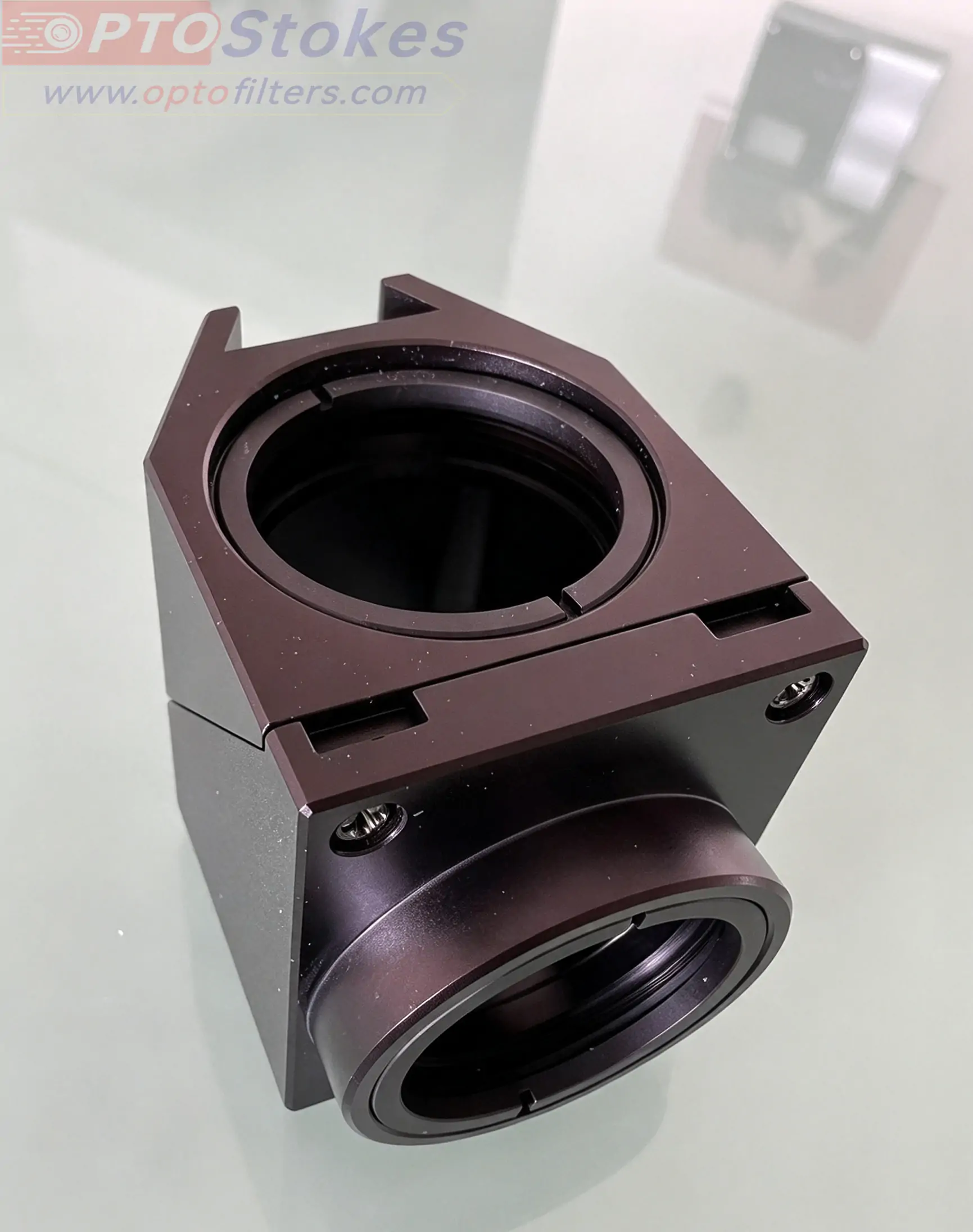
An epi-fluorescence cube carries the entire spectral workflow of the microscope inside a block the size of a matchbox. Excitation and emission share the same optical axis but travel in opposite directions, and the dichroic mirror is what separates them.
Excitation: source → excitation filter → dichroic mirror (reflected) → objective → sample.
Emission: sample → objective → dichroic mirror (transmitted) → emission filter → PMT or camera.
Each element has one spectral job and one preferred direction of light. Orientation follows from the path, not from habit.
| Component | Position in the path | Spectral task | Working principle |
|---|---|---|---|
| Excitation filter | Between source and dichroic mirror, normal to the beam | Transmits the excitation band, blocks the rest of the source spectrum and stray light | Bandpass interference coating, forward transmission |
| Dichroic mirror | Centre of the cube, 45° to both paths | Reflects the excitation band, transmits the emission band | Selective reflective and transmissive coating on an inclined face |
| Emission filter | Between dichroic mirror and detector, normal to the beam | Transmits the emission band, blocks residual excitation and background | Bandpass interference coating, forward transmission |
Two Coating Architectures, Two Sets of Rules
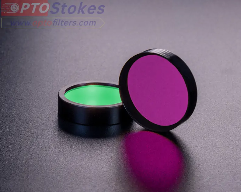
Before deciding which face points where, confirm which architecture the part uses. The two common builds assign different roles to the two faces, so the installation direction differs.
| Architecture | Input face | Output face | Coating role |
|---|---|---|---|
| A — filter coating + AR | Filter coating | AR coating | Spectral selection on one face, Fresnel reduction on the other; standard catalogue build |
| B — bandpass + blocking | Bandpass coating | Blocking coating | Both faces active; second suppression of out-of-band energy |
Architecture A is the standard build: one face does the spectral work, the other is an antireflection coating that reduces reflection loss at the glass-air interface. Architecture B puts functional coatings on both faces, with a bandpass coating selecting the passband and a blocking coating suppressing out-of-band light a second time.
If the datasheet does not state the architecture, ask. Judging from appearance is unreliable, because an AR coating and a blocking coating can look identical under room light.
Reading the Markings on the Shell
Mounted filters carry markings for one reason: they are the first line of defence against a reversed installation. Two conventions exist, and they do not mean the same thing.
Arrow on excitation and emission filters
The arrow shows the recommended direction of light travel. Light enters at the tail and leaves at the tip, so the arrow should point the way the beam travels: tail toward the source or the sample, tip toward the dichroic mirror or the detector.
Triangle on dichroic mirrors
A triangle or dot on a dichroic mirror points at the coated face. It marks a position, not a direction. The beam should strike the marked face first, because that is where the interference stack sits.
Mixing the two conventions is the most common error in a service lab. An arrow tells you where light goes. A triangle tells you where the coating is.
Excitation Filter: Coating Toward the Source
The excitation filter sits between the source and the dichroic mirror and defines the excitation band. Its coating faces the source.
| Architecture | Input face (source side) | Output face (dichroic side) |
|---|---|---|
| Afilter coating + AR | Filter coating (arrow tail) | AR coating (arrow tip) |
| B bandpass + blocking | Bandpass coating | Blocking coating |
The reasoning is thermal as much as optical. Stray light and the blocked band reach the first coating and are reflected back toward the source instead of being absorbed in the glass. The substrate stays cooler, and it does not generate the broadband autofluorescence that a heated substrate produces.
One exception exists. Where the blocked band carries very high energy on the source side and the main coating has limited damage threshold, the blocking coating can be placed on the input face. That is a special case, not a default, and standard fluorescence systems should follow the rule above.
Emission Filter: Coating Toward the Sample
The emission filter sits between the dichroic mirror and the detector. Its coating faces the sample side.
| Architecture | Input face (sample side) | Output face (detector side) |
|---|---|---|
| A — emission coating + AR | Emission coating (arrow tail) | AR coating (arrow tip) |
| B — bandpass + blocking | Bandpass coating | Blocking coating |
Two details matter at the detector end. The exit face should look at the detector window to keep interface reflections low. And leave an air gap between the filter and that window: clamping the two surfaces together forms an etalon, and the fringes appear as spectral ripple and as fixed-pattern artefacts in the image.
A reversed emission filter is worse than a reversed excitation filter. Residual excitation crosses the substrate before it is blocked, the glass heats, and the substrate fluoresces. Background rises, signal-to-noise falls, and the loss is regularly misdiagnosed as a weak lamp or an ageing detector.
Dichroic Mirror: 45°, Coating Toward the Excitation Side
The dichroic mirror sits at the centre of the cube, inclined at 45° to both paths. It reflects the excitation band and transmits the emission band, and the edge position plus the coating face determine how cleanly it does so.
Three points cover the installation. The mirror must sit at 45° to each path with no tilt in the mount. The coating faces the excitation input. The marked triangle and the coated face stay on the same side.
A dichroic installed backwards produces a signature that is easy to recognise: excitation leaks toward the detector while the fluorescence signal drops sharply.
What a Reversed Filter Costs
The same filter, installed the two ways, differs mainly in whether stray light enters the glass before it is blocked.
| Correct installation — coating toward the light | Reversed installation |
|---|---|
| Stray excitation strikes the first coating and is reflected back toward the source or the dichroic mirror. | Residual excitation crosses the substrate first and is absorbed there, heating the glass. |
| The substrate carries no blocking load, so it neither heats nor fluoresces. | The heated substrate fluoresces, raising background and flattening contrast. |
| The passband transmits cleanly through the exit coating with low interface loss. | The reflective face points at the exit side, adding interface reflections and interference fringes. |
A quick field test: if the background is uniformly grey and noisy, and turning the filter around improves the signal noticeably, orientation was the fault. Gain and lamp hours can wait.
Five Steps, Then Verify
The sequence is the same for all three elements: read the marking, set the direction, lock down, verify.
| Step | Action | What good looks like |
|---|---|---|
| 1 | Confirm part number and marking | Three elements belong to one set; arrow or triangle has been read correctly |
| 2 | Handle the mount, not the glass | Fingers touch the metal ring only |
| 3 | Insert in the correct direction | Arrow follows the beam, coating faces the input, dichroic stays at 45° |
| 4 | Lock and align | Retaining ring evenly seated, no tilt, no decentre |
| 5 | Power up and check | Expected signal level, clean background, no fringes, no leak |
| Practice | Prohibited |
|---|---|
| Wear lint-free gloves and work in a clean area. | Do not touch the coated surface with bare hands. |
| Clean the coating with lens tissue or clean compressed air before fitting. | Do not tilt the filter; the dichroic must stay at 45°. |
| Keep an air gap between the filter and the detector window. | Do not stack two filters in contact, which creates etalon fringes. |
| Face the label outward so the next person can identify the part. | Do not mix elements from sets built for different fluorophores. |
Quick Reference
| Element | Shell marking | Input face (light side) | Output face (detector side) | Note |
|---|---|---|---|---|
| Excitation filter | Arrow = direction of travel; tail in, tip out | Filter or bandpass coating (arrow tail) toward the source | AR or blocking coating (arrow tip) toward the dichroic | Stray light is reflected before it reaches the substrate |
| Emission filter | Arrow = direction of travel; tail in, tip out | Emission or bandpass coating (arrow tail) toward the sample | AR or blocking coating (arrow tip) toward the PMT or camera | Keep an air gap at the detector window |
| Dichroic mirror | Triangle points at the coated face; marks position | Coated face toward the excitation input, at 45° | Transmission side toward the emission path | 45° to both paths; never mounted perpendicular |
The Substrate Is Part of the Specification
Most orientation discussions stop at the coating. Buyers working on high-NA systems learn to look further, because the substrate sets limits the coating cannot correct. Transmitted wavefront error, parallelism, surface flatness, and thickness tolerance all feed into image quality, particularly in confocal and super-resolution builds. Our optical flats and laser windows are specified on these parameters rather than on diameter alone.
| Parameter | Why it matters | What to confirm |
|---|---|---|
| Transmitted wavefront error | Bends the wavefront passing through the filter | Value at the design wavelength, over the clear aperture |
| Parallelism | Wedge steers the beam and shifts the image | Specified per part, with the measurement method stated |
| Surface flatness | Affects coating uniformity and focus | Fraction of a wavelength at 633 nm, over the clear aperture |
| Thickness tolerance | Sets the optical path and the fit in the holder | Tolerance range and how it is measured |
| Surface quality | Scatter raises background in low-light imaging | Scratch-dig per surface, both faces |
Sets, Not Single Filters
Excitation, emission, and dichroic are matched to a fluorophore and to each other. Swapping one element from a different set produces spectral mismatch: excitation bleed-through, reduced collection efficiency, or a background step that no amount of frame averaging removes. Change the dye, change the set.
Our fluorescence filter sets ship as matched triples with published spectra, so the crossover between dichroic mirrors and the two bandpass elements is defined rather than assumed.
Standard or Custom
Catalogue cubes cover the common fluorophores: FITC, TRITC, Cy5, DAPI, and the usual GFP variants. Beyond that, applications tend to need something specific — a non-standard excitation line, a shifted band position, a particular mounted diameter, a higher blocking level, or a substrate thickness that fits an existing holder.
Custom work covers coating design, substrate selection, mounting, and spectral measurement against the drawing. Lead time is quoted against a defined stack rather than a general category, which is the only basis on which a project schedule can be trusted.
Talk to an Optical Engineer
When a cube underperforms and orientation has been ruled out, the next questions are usually about the set, the substrate, or the match between them. Send the fluorophore, the excitation source, and the current filter specifications, and we will identify where the loss originates — including the cases where the honest answer is that the existing set is a reasonable choice.
For technical consultation, samples, or a quotation, write to sales@optofilters.com or submit an enquiry through the website. Drawings and spectral requirements are welcome at first contact; they shorten the loop on both sides.