
Product Description
BP10430nm long wave infrared bandpass filter: 10.43 μ m, 0.5mm thick, 400-16000nm blocking
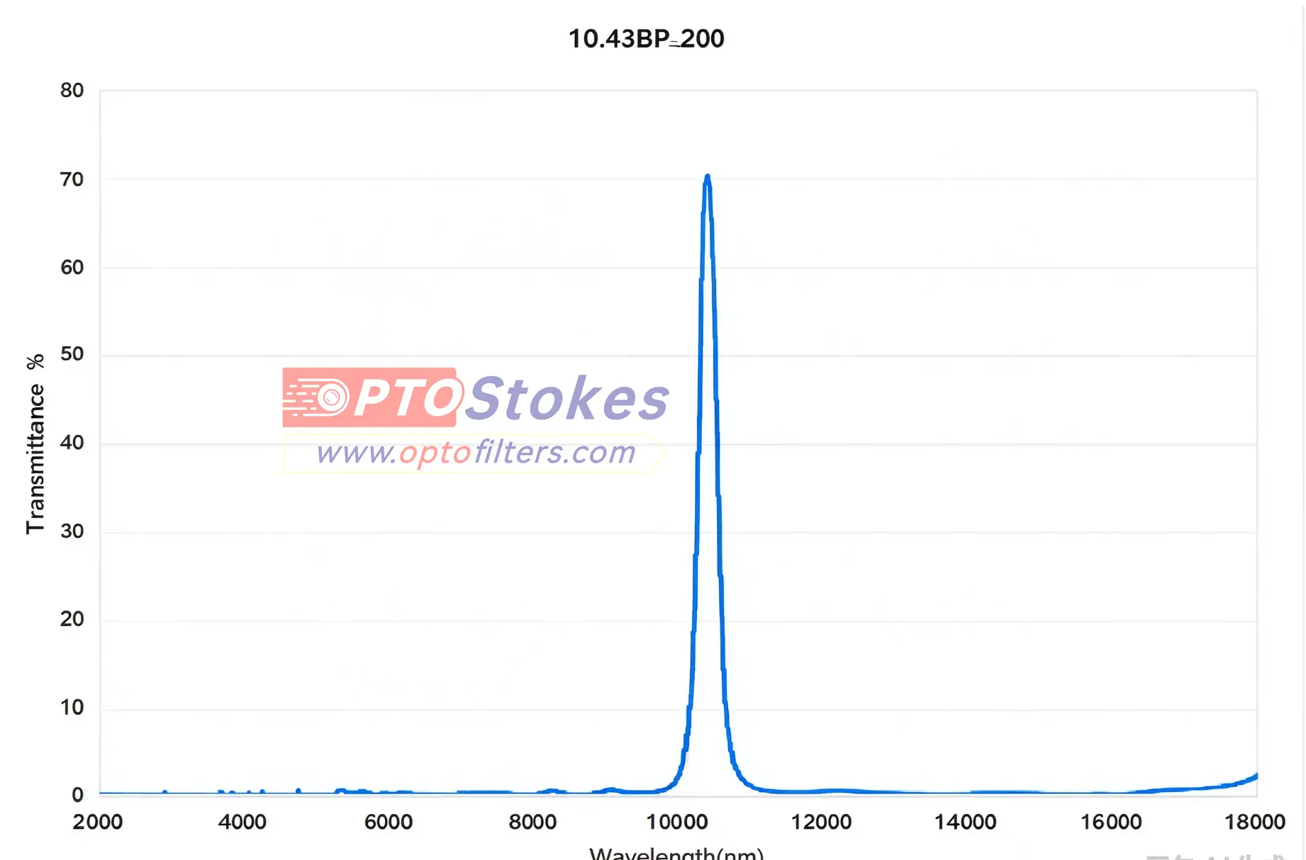
BP10430nm is a long wave infrared bandpass filter with a center wavelength of 10.43 μ m and a thickness of 0.5mm, used for band selection in industrial temperature measurement and high temperature monitoring optical paths. There are very few optional materials for this band - only a few can pass through substrates with a thickness of 10.43 μ m. Once the materials are chosen incorrectly, no matter how well the film system is made, it is useless.
Technical specifications
| Parameters | Specifications | Description |
|---|---|---|
| Product model | BP10430nm | The wavelength is subject to the following table |
| Center wavelength CWL | 10430nm (10.43 μ m) | Transmittance at this wavelength T>; 90% |
| FWHM | This page does not provide | The measured curve shall prevail |
| Blocking range | 400-16000nm (excluding passband), OD> 2 | OD2 corresponds to a transmittance of 1% |
| Base material | Silicon wafer | Band matching is described below |
| Incident angle | 0 ° | Other working angles need to be confirmed separately |
| Thickness | 0.5mm | Single substrate thickness |
| Appearance/Dimensions | Confirm according to inquiry | No fixed specifications specified on this page |
The blocking interval is written as "passband excluded": 10.43 μ m falls within the range of 400-16000nm, and the blocking commitment refers to the entire segment outside the passband. In addition, this page does not provide the full width at half maximum - the bandwidth of a bandpass filter determines how many adjacent wavelengths it can pass through, which cannot be bypassed during selection and needs to be confirmed according to the measured curve.
The substrate step is more prone to errors than the membrane system
The specifications are for silicon wafers, and there is one thing that must be checked: the transmission window of optical silicon is roughly between 1.2-7 μ m. After exceeding 7 μ m, the absorption of lattice vibrations rapidly increases, and by 10.43 μ m, it is close to opacity. That is to say, a 0.5mm thick silicon wafer cannot achieve 90% transmission at 10.43 μ m, and these two parameters cannot be held simultaneously.
There are only a limited number of transmissive materials available for long wave infrared energy: germanium (about 2-14 μ m), zinc selenide (about 0.6-21 μ m), zinc sulfide (about 0.4-12 μ m), and barium fluoride (about 0.15-12 μ m). The window of germanium is the most suitable for this specification - it covers a range of 2-14 μ m, with natural cutoff at both ends, which is highly consistent with the blocking range of 400-16000nm. 0.5mm is also the conventional thickness of germanium sheets.
So whether the actual substrate is silicon, germanium or other materials needs to be verified with the supplier before finalizing. This is not a matter of wording: if the material selection is wrong, the transmittance will be directly reset to zero, not discounted. There are several issues with the long wave infrared filter in this step out of ten times.
One thing that comes with a thickness of 0.5mm
0.5mm is a conventional thickness in this band, and both mechanical strength and heat capacity are well controlled. It also brings a side effect: the two surfaces of the substrate form a Fabry Perot cavity, and periodic ripples are superimposed on the spectrum. The higher the refractive index, the denser the ripple - if the substrate is germanium with a refractive index of about 4.0, the ripple interval corresponding to a thickness of 0.5mm is approximately 2-3 wavenumbers (cm ⁻¹). The impact on broadband temperature measurement is minimal, but it will become apparent in high-resolution spectral measurements. If the system is sensitive to ripple, the filter can be installed slightly tilted or baseline subtraction can be performed during the data processing stage.
Industrial temperature measurement: a parameter based selection deduction
The following is a deduction example, not a customer case.
Requirement: Continuous temperature measurement channel for industrial sites, measuring the surface of moving workpieces or furnace bodies. The detector is a pyroelectric or microcalorimeter, and stable output is required in workshops with dust and background heat sources.
Why 10.43 μ m: It falls within the atmospheric window of 8-14 μ m, which is where the radiation from objects at room temperature is strongest. The medium to low temperature target has the strongest signal here, and the open light path will not be fragmented by water vapor and carbon dioxide absorption bands. The cost is that long wave temperature measurement is more sensitive to emissivity settings and environmental background radiation, requiring accompanying environmental temperature compensation.
A reminder about the temperature range: The temperature corresponding to the peak of blackbody radiation at 10.43 μ m is around 5 ℃, and its strength lies in the normal to medium temperature range. If the target temperature is above 800 ℃ and the radiation peak has shifted to within 3 μ m, the signal-to-noise ratio and tolerance for emissivity errors of the shortwave channel will be better. Which band to choose depends on the material being tested and the temperature range, not the more "far-infrared" the better.
Why do we need to see a blocking range of 16000nm? Thermal detectors are broadband, responding from visible light to just over ten micrometers. The filter does not just need to block a certain line, but needs to compress the entire section that the detector can respond to, otherwise stray radiation from the light source and environmental thermal background will mix into the reading.
Applicable boundary: collimated optical path, 0 ° incidence; The tested target fills the field of view; The ambient temperature is relatively stable or has been compensated for.
Before placing an order, it is necessary to verify the substrate material and its actual transmission at that wavelength; Blocking curve for the entire range of 400-16000nm; Is the detector response range aligned with the blocking range.
Two easily trampled misjudgments
One is to ignore that the filter itself also emits radiation. There is a fundamental difference between the 10 μ m band and shortwave infrared: in this band, objects at room temperature are themselves strong radiation sources. The casing, lens barrel, aperture, and even the filter itself are all delivering energy to the detector. Insufficient blocking or the presence of metal components in the optical path that have not been temperature controlled will result in an overall high reading, and this high reading will drift with the ambient temperature, appearing as "instrument instability", but in reality, thermal radiation has entered. The correct approach is to include all surface temperatures within the optical path in the calculation, and if necessary, perform temperature control on the optical aperture, rather than just focusing on the OD number of the filter.
The second is to select the wavelength roughly based on the four words "infrared temperature measurement". 10.43 μ m, 1.6 μ m, and 3.9 μ m face completely different operating conditions: target temperature, emissivity, environmental background, and detector type, each of which will push the selection in different directions. The optimal wavelength for measuring plastic surfaces at 50 ℃ and steel billets at 1200 ℃ for the same "infrared temperature measurement" requirement is one order of magnitude different. First, determine the temperature range and the material being measured, then talk about the wavelength. If the order is reversed, it needs to be redone.
Customization and delivery support
The center wavelength and bandwidth can be adjusted according to the project, the substrate material (germanium, zinc selenide, zinc sulfide, etc.) can be specified, the anti reflection design can be optimized, the blocking interval can be expanded, the thickness and shape can be changed, and the set of card rings can be matched. Samples and measured spectral data can be provided by project. Batch applications require agreement on the acceptance aperture for center wavelength tolerance and minimum blocking value - batch consistency in long wave infrared is more difficult to control than in visible bands, and this should be written into the protocol rather than verbally confirmed. The selection ideas for long wave infrared filters in the same wavelength band can be referred to in<a href=“ https://www.optofilters.com/article/case/LWIR-Filter-Selection-for-NH3-Sensors.html Selection case of 10.45 μ m long wave infrared filter; for more infrared bandpass specifications, please refer to<a ref= https://www.optofilters.com/product/OpticalFilters.html Classification of Optical Filter Products
Information required for inquiry
Please provide: center wavelength and bandwidth, temperature range and material (emissivity) of the measured target, substrate material requirements, detector model and response range, optical path and ambient temperature, external dimensions and aperture, annual usage. The bandwidth in the first line and the temperature range in the second line are the most critical - the former determines how many adjacent wavelengths it can accommodate, while the latter determines whether 10.43 μ m is the correct band. Technical Consultation and Inquiry: sales@optofilters.com , or through<a ref=“ https://www.optofilters.com/single/contact-us.html Contact us on thepage to submit.
Tags: 10430nm infrared filter long wave infrared bandpass filter LWIR filter industrial temperature measurement filter BP10430nm