Overcoming Thermal Drift in Precision Optical Flats and Bandpass Filters
During system calibration in optical inspection, machine vision, and spectroscopic analysis, field engineers often encounter a persistent issue: an optical system calibrated perfectly at room temperature experiences signal attenuation and baseline measurement drift as operational temperatures rise. After inspecting the excitation light sources, detectors, and signal amplification circuits, the failure is frequently traced back to the optical component itself.
While this performance degradation is often mistaken for a glass manufacturing defect, it is actually a physical manifestation of thin-film thermal drift. Precision components—including coated Precision Optical Flats and thin-film interference filters—exhibit predictable optical property shifts under environmental temperature variations.
Physical Mechanisms Driving Temperature Drift
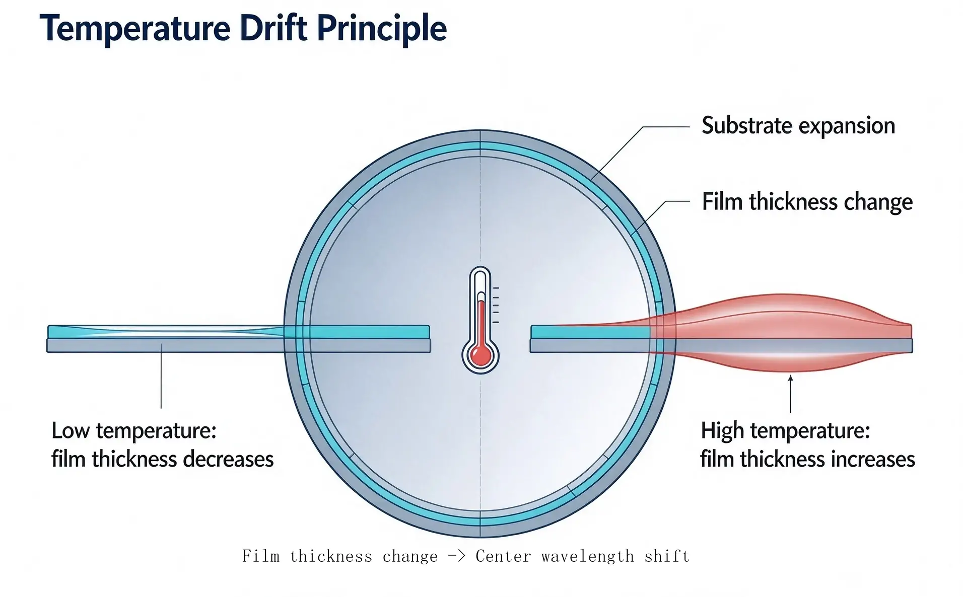
The drift of center wavelength (CWL) in coated optics stems fundamentally from the Coefficient of Thermal Expansion (CTE) mismatch between dielectric coating materials and the underlying substrate glass. Optical thin-film structures consist of alternating high-index ($n_H$) and low-index ($n_L$) dielectric layers. As ambient or operational temperatures change, both the substrate and thin-film layers expand or contract at different rates, directly altering physical layer thickness and refractive index .
Because the transmitted peak wavelength of interference coatings is directly proportional to the optical thickness ($n \times d$) of the dielectric layers, thermal variance shifts the spectral transmission curve:
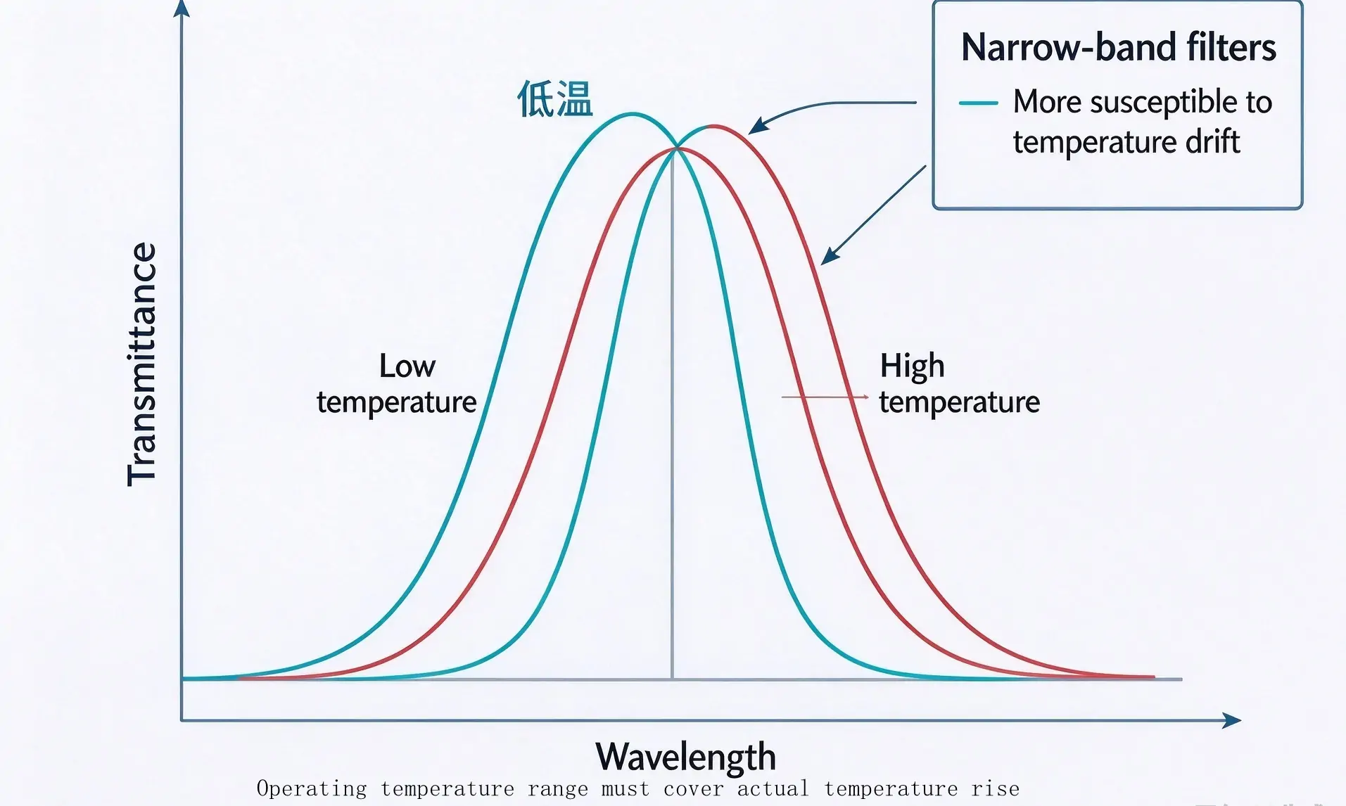
Temperature Elevation: Physical layer expansion and index shifts move the spectrum toward longer wavelengths (red-shift).
Temperature Reduction: Contraction shifts the transmission profile toward shorter wavelengths (blue-shift).
| Optic Category | Typical Thermal Drift Coefficient | Impact on Optical Performance |
|---|---|---|
| Standard Dielectric Bandpass Filters | 0.01 – 0.03 nm/°C | Moderate transmission shift; minor effect on broad passbands. |
| Ultra-Narrow Bandpass Filters (FWHM ≤ 5nm) | 0.01 – 0.03 nm/°C | Critical signal loss if source emission shifts outside the tight passband window. |
| Edge Filters (Longpass / Shortpass) | 0.015 – 0.035 nm/°C | Cut-on/cut-off edge displacement affecting fluorescence detection. |
For narrow-band applications where Full Width at Half Maximum (FWHM) is restricted to a few nanometers, even a 2 nm shift can push the light source emission outside the filter passband, resulting in catastrophic signal degradation. Longpass and shortpass filters exhibit higher tolerance due to broader spectral bands, making narrow passband optics the most sensitive to thermal variance.
Common Selection Oversights in Engineering R&D
A frequent mistake during the prototype stage is evaluating optical performance exclusively under ambient room temperature ($20^\circ\text{C} - 25^\circ\text{C}$). System designers often overlook internal thermal accumulation caused by closed enclosures, light source dissipation, and severe seasonal ambient changes.
When field units display inconsistent measurement baselines between summer and winter operational environments, spectral temperature drift in the optical path is routinely identified as the primary failure mode.
Engineering Strategies to Mitigate Thermal Drift
Athermal Coating Stack Design: Utilize optimized, low-drift coating designs with stress-compensated dielectric materials to compress the thermal expansion coefficient.
Thermal Management & Optomechanical Dissipation: Optimize chassis heat sinking near the optical mount to prevent local heat accumulation around sensitive optical elements.
Bandwidth Margin Allocation: Avoid tight bandwidth specifications when operating in un-tempered environments; reserve sufficient spectral margin for predicted wavelength wander.
Closed-Loop Thermal Control: For high-precision analytical instruments, incorporate TEC (Thermoelectric Cooler) modules to stabilize the immediate environment of the optical flat or filter.
Thermal Reversibility vs. Permanent Coating Damage
It is vital to distinguish functional wavelength shift from coating degradation. Spectral shift is fully reversible once operating temperatures return to baseline values. However, prolonged thermal cycling combined with elevated thermal expansion stress can cause cumulative mechanical strain within the dielectric stack. Over extended operational lifespans, unmitigated thermal stress increases the risk of micro-cracking, delamination, and irreversible optical degradation.
In high-reliability system engineering, spectral verification must include high-and-low temperature chamber scans over the complete operating range. Evaluating parametric stability under realistic thermal stress ensures long-term system dependability.
Technical Support & Custom Athermal Solutions
Engineering robust optical systems requires selecting components verified for thermal stability. OPTOStokes offers extensive in-stock inventories and custom thin-film coating services tailored to strict environmental requirements. Whether you require temperature-stabilized narrow bandpass filters or precision optical flats engineered for harsh operating environments, our engineering team provides comprehensive spectral testing and reliable volume supply.
For technical inquiries, custom coating consultations, or sample requests across complete operating temperature ranges, contact our engineering specialists directly at sales@optofilters.com or submit your specifications via our website inquiry form.